CXL 2.0 Switching and Memory Disaggregation
Introduction
CXL 2.0 introduces switching that allows multiple hosts (CPUs) to access partitions of memory within multiple type 3 devices (that use the CXL.mem protocol). The memory partitions within devices are memory mapped, hosts can make memory requests to these locations which are then routed by the switch to appropriate memory partition.
This switching is reconfigurable and provided by a CXL 2.0 switch that has a standardized fabric manager. The fabric manager provides APIs to bind memory partitions to hosts. Note that for devices that use CXL.cache protocol, there is no switching possible and one host has to be connected to one device.
In CXL nomenclature, a logical device is an useful abstraction of a device and its internal memory, which will be described next.

Logical devices: Single and Multiple
Each device has some internal memory that is to be accessed by hosts. This internal memory is memory mapped to the 64-bit host address space. Viewing the device as a bunch of memory that is mapped to a specific address range is an useful abstraction and is called logical device.
Depending on how the memory within the device is partitioned, the devices can be viewed as either a single logical device (aka logical device) or multiple logical device. In a single logical device, the memory within the device is not partitioned. This means that this memory is not distributed between the hosts whereas in a multiple logical device, the memory within is partitioned between different hosts thereby allowing disaggregation.
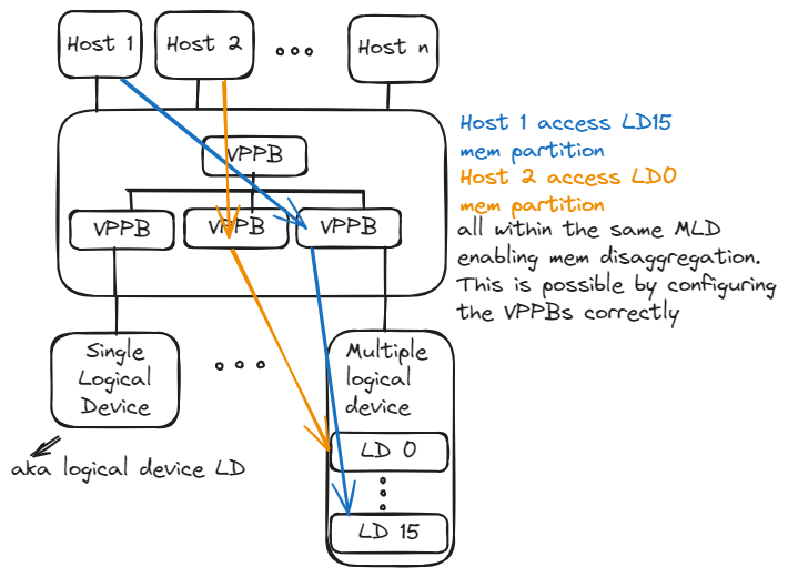
As shown in figure below, the memory within a multiple logical device is partitioned into 16 memory partitions (logical devices), each partition is accessible to a host through the CXL 2.0 switch (and its fabric manager). For example, the logical devices LD0 and LD15 can be configured to be accessible by hosts 2 and 1 respectively. Isolation between hosts and logical devices (so that multiple hosts do not access the same logical device within a MLD) is the responsibility of the switch and the device.

Next lets look at how hosts can access memory within a logical device
Switching and routing of memory requests and memory disaggregation
Whenever the host wants to access a memory location within a logical device, it issues a memory request to the memory mapped address of this location. The switch has the necessary information to identify which logical device this request is directed to and routes the request appropriately. The response from the device is then routed back to the host.
Internally, the virtual view of a CXL 2.0 switch is shown in figure below. A virtual CXL switch (VCS) can be viewed as a tree of virtual PCIe to PCIe bridge (VPPB) which has information on which memory address resides on what downstream VPPB and logical device. Thus a request received by a VPPB will be routed to the appropriate downstream VPPB and eventually reach the logical device

The VPPBs can be configured to access a specific logical device within a multiple logical device. This allows multiple hosts to access different partitions of the memory within the same multiple logic device as shown in figure below. This is how it enables memory disaggregation.

Thus to ensure isolation, each leaf VPPB should be connected to only one logical device.
CXL Fabric Manager
The CXL fabric manager provides APIs to link hosts to logical devices.
Summary
- CXL switches and fabric manager allow multiple hosts to access partitions of memory within type 3 devices (cxl.mem devices).
- The memory partitions within devices are memory mapped, hosts can make memory requests to these locations which are then routed by the switch to appropriate memory partition.
- The CXL fabric manager provides APIs to program the CXL switch with the routing information.